The Internal Block Diagram
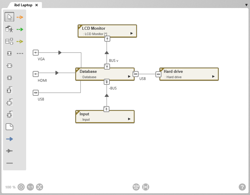
An internal block diagram describes the structure and flows within a block. Internal block diagrams provide a simple overview of how the parts of a block interact and what kind of data, information, signals or materials flow in which directions. It represents what happens inside a block.
The most important editing functions
| Add Existing Elements Enables requirements and interfaces that have already been created to be included in the diagram. First click on the button and then on a free space in the diagram. | |
| Add Child ElementsEnables ports, parts and interfaces to be taken over directly. First click on the button and then on a free space in the diagram. | |
| Create Port | |
|
Create Standard Port A standard port defines an interaction point of a part. It specifies that a block of services (service(ces) requests or offers. The type of port is specified by creating a realized or used relationship to an interface. In the diagram, square boxes bordered in gray show a standard port. Standard ports of parts are marked with a dot in the upper left corner of the port symbol. Ports without a dot show ports of the block whose inner workings show the internal block diagram. |
|
|
Create Flow-Port A flow port defines an interface through which objects of any kind can be exchanged between blocks and between parts. A distinction is made between atomic and non-atomic flow ports.
Flow ports of parts are marked with a dot in the upper left corner of the port symbol. Ports without a dot show ports of the block whose inner workings are shown in the internal block diagram. |
|
| Create Port on Part | |
| Create Standard Port on Part | |
| Create Flow Port on Part | |
| Create Note | |
| Create Generalization A generalization visualizes a relationship between a general and a specific element. The special element inherits all the properties and behavior of the general element and also has additional behaviors and properties. Generalizations between interfaces can be created in the internal block diagram. Generalizations are represented by a blue line with an arrow. The arrowhead points to the general (inheriting) element. | |
| Create Itemflow | |
| Create Connector Connectors are used to connect blocks directly or via ports. They show that information, data or signals, material, energy etc. are exchanged between blocks or their parts. Connectors are visualized by a grey relationship line. | |
| Create Use Relationship A use-relationship is created between a standard port of a part and an interface. It expresses that the block uses the interface. This relationship is represented by an orange dotted line with an open arrowhead, the arrowhead pointing to the interface. | |
| Create Realize Relationship A realized relationship is created between a standard port of a part and an interface. It expresses that the block realizes or offers the interface. This relationship is represented by a green dotted line with a closed arrowhead, with the arrowhead pointing to the interface. | |
| Create Satisfy Relationship A fulfillment relationship documents which part of a requirement is fulfilled. A fulfillment relationship is an olive-green dotted line with an arrow. The arrowhead points to the fulfilling requirement. The standard stereotype for a fulfillment relationship is “satisfy”. | |
| Create Note Relationship Associates a note with another chart item. |