
The State Machine Diagram
This diagram type is not supported in the web client.
Diagram
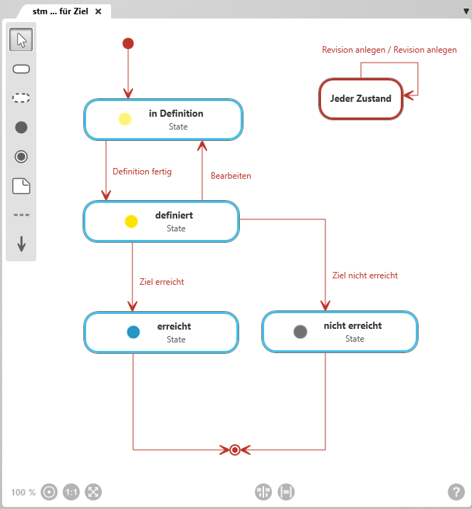
Toolbar
A toolbar is available on the left side of the diagram for working in the diagram. This toolbar is used to create elements and relationships and to add existing elements to the diagram. A tooltip indicates which elements and relationships can be created with a button when you move the mouse pointer over the button.
Elements that are created in a diagram are created in the package in which the diagram is also located.
Permitted diagram elements
New elements are always created according to the same principle: Click the button and then click in the diagram. A creation dialog opens, and as soon as the dialog is confirmed, the element is displayed in the diagram.

With the selection tool (arrow), you can:
- Move the diagram background: Click the diagram background and drag it to another position while holding down the left mouse button.
- Edit diagram elements and relationships: Right-click a diagram element or relationship to open the context menu.
- Select diagram elements: Hold down the Shift key and use the left mouse button to drag a frame around the desired element nodes. Selected nodes are highlighted. Click the diagram background to clear the selection.

Create state
Indicates the state an element can be in for a certain period of time before it transitions to another state.
In the state itself, you can use Edit to define various actions, guards, and events. You determine the order in which states are passed through using state transitions.
Procedure for creating: Click the button and then click the diagram background.
Representation: State node with a blue border
Supported link: Start node, end node, state

Any state
Used to create a state so that state transitions can be provided for all states in the diagram.
This state cannot be configured or renamed.
Procedure for creating: Click the button and then click the diagram background.
Representation: State node with a red border
Supported link: itself, state,

Create start state
Indicates the beginning of a state machine.
A diagram must contain at least one start node.
Procedure for creating: Click the button and then click the diagram background.
Representation: filled red circle

Create end state
Indicates the end of a state machine. Multiple end states can be created.
Procedure for creating: Click the button and then click the diagram background.
Representation: red circle with a filled dot

Create note
Used to create a note to provide additional information about the diagram or a diagram element.
Procedure for creating: Click the button and then click the diagram background.
Representation: Note node
Supported link: all permitted diagram elements

Create transition
Connects two states and thus defines which state can be transitioned to.
Guards and actions can be defined for state transitions and executed before, during, or after a transition. The defined actions, events, and guards are shown on the relationship line.
Procedure for creating: Click a state (or start node) and then click the subsequent state.
Representation: red line with arrow
Arrow direction: arrowhead points to the subsequent state

Create note relationship
Connects a note to another diagram element.
Procedure for creating: Click the note and then click the element node that is described in more detail by the note.
Representation: gray dashed line
Example "Start state"
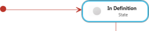
Start state with transition and state. As soon as an element for which the state machine is defined is created, it automatically enters the In Definition state.
Example "End state"
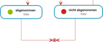
States with transitions and end state. The execution of the state machine ends when either of the two states abgenommen or nicht abgenommen is reached. The element for which the state machine is defined reaches its respective end state.
Example "Transition"
![Transition mit Ereignis (In Auftrag geben), Bedingung ([Zustandsprüfung]) und Aktion (Element benachrichtigen).](https://manual.microtool.de/wp-content/uploads/2018/01/example-transition.png)
Transition with event (In Auftrag geben), guard ([Zustandsprüfung]) and Action (Element benachrichtigen). You specify and edit events, guards and actions in the Properties dialog of the transition.
Example "State"

The state beauftragt with its icon and stereotype (state).