The State Machine Diagram
Which state will be reached and when? Which event will trigger the state transition? In a State Machine, all states of an element are described. The machine describes which events occur or which guards have to be in place, so that a state transition is made. It also describes which actions will be taken, when a state transition occurs or a state is reached.
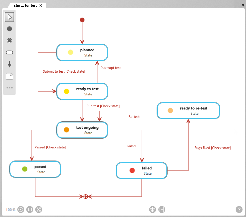
The diagram
The most important editing functions
| Create Initial State Used to create start states that are directly transferred to the diagram. Describes the start of the processing of a state machine and its outgoing transition (event). | |
| Create Final State This button creates a final state and adds it to the diagram. | |
| Create State This button creates a new state and adds it to the diagram. States correspond to a situation, in which a specific guard applies. A state is entered when a transition is made of which the state is the end point. A state is left, when a transition is made that leads away from the state. The symbol of a state shows its icon and its stereotype. The default stereotype of states is «State». | |
| Create Transition This button creates a new transition and adds it to the diagram. A transition defines a change from one state to an other. For transitions, you can create Guards, which have to be in place; and events, which have to occur before a transition in state occurs; and actions, which have to be taken when the transition occurs or a state is reached. The default stereotype for this kind of relationship is «TransitionType». On the relationship line, Events, followed by guards, and actions are displayed. |