
The System Context Diagram
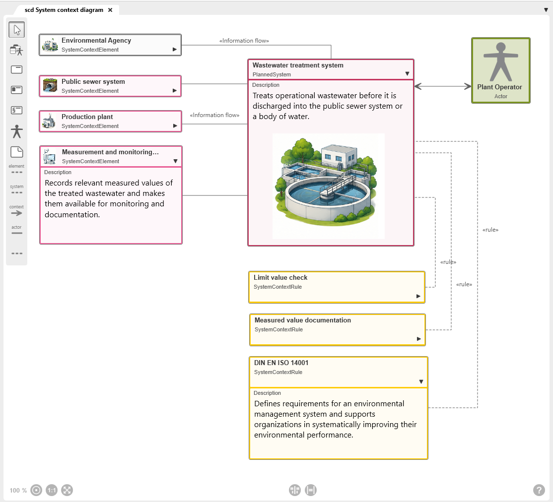
The system context diagram is used to define the boundaries of the system to be developed and to represent its environment (context). It shows what belongs to the system and which elements lie outside the system boundary.
In addition, this diagram type shows:
- which interaction partners are connected to the system
- which information flows between the system and its context elements
- which constraints, standards, and rules must be taken into account during system development.
For these reasons, a system context diagram should be created at the beginning of a project. The diagram is also suitable for communication with stakeholders and specialist departments.
The diagram
Toolbar
A toolbar is available on the left side of the diagram for working in the diagram. This toolbar is used to create elements and relationships and to add existing elements to the diagram. Which elements and relationships can be created with a button is shown in a tooltip when you move the mouse over a button.
Elements that are created in a diagram are created in the package in which the diagram is also located.
Alternatively, elements of the system context diagram can also be added to the diagram via drag & drop from a view or any package.
Permissible Diagram Elements
Not all element types can be used in this diagram type. The permissible diagram elements are determined by the system context shown as well as by the rules and context elements defined for it. Accordingly, the diagram type supports only the element types intended for this purpose.
In the Desktop Client, all buttons provided by the respective diagram type for creating elements and relationships are displayed.
In the Web Client, the toolbar has a more compact layout. Only some of the buttons are displayed directly. Additional element types and relationships are grouped and can be accessed via the context menu of a button. Buttons with additional options are indicated by a dot in the lower-right corner.

White arrow
With the selection tool (arrow), you can:
- Move the diagram background: Click the diagram background and drag it to another position while holding down the left mouse button.
- Edit diagram elements and relationships: Right-click a diagram element or relationship to open the context menu.
- Select diagram elements: Hold down the Shift key and use the left mouse button to draw a frame around the desired element nodes. Selected nodes are highlighted. Click the diagram background to clear the selection.

Add Existing Elements
Opens a selection dialog to add existing system context diagram elements to the diagram.

Create System
Is the central element of the system context diagram and represents the system to be developed
Procedure for creating: Click the button and then click the diagram background.
Representation: System node
Supported link: Actor, rule, system context elements

Create System Context Element
Represents a part of the system and is located either inside or outside the system context.
- Elements inside the system context have the same color as the system context.
- Elements outside the system context are displayed in gray.
Procedure for creating: Click the button and then click the diagram background.
Representation: Context element node
Supported link: System, rule

Create Rule
Rules (legal regulations, standards) that must be taken into account during system development
- Procedure for creating: Click the button and then click the diagram background.
- Representation: Rule node
- Supported link: System, context element

Create Actor
Users, devices, or external systems that interact with the system
Procedure for creating: Click the button and then click the diagram background.
Representation: Actor node
Supported link: System

Create Note
Used to create a note to provide additional information about the diagram or a diagram element.
Procedure for creating: Click the button and then click the diagram background.
Representation: Note node
Supported link: Possible with all permissible diagram elements

Create Element-Rule Relationship
Connects a rule to a system context element.
The default stereotype of this relationship type is «rule» and is displayed on the relationship line.
Procedure for creating: Click the rule and then click the context element.
Representation: dashed gray line

Create System-Rule Releationship
The default stereotype of this relationship type is «rule» and is displayed on the relationship line. The name can be changed.
Procedure for creating: Click the rule and then click the system.
Representation: dashed gray line

Create Information Flow
Connects the system to a system context element and shows that information is exchanged between the system and its context elements.
The default label of the relationship is Information flow and is displayed on the relationship line. The name can be changed.
Procedure for creating: First click the system context element and then click the system. In the relationship editing dialog, you can specify whether the exchange is incoming, outgoing, or both.
Representation: gray line
Arrow direction: The arrowhead indicates the direction of the exchange and points to the system, the context element, or both

Create Interact Relationship
Expresses that an actor interacts with the system
The relationship can be labeled.
Procedure for creating: Click the actor and then click the system.
Representation: gray line with an arrow on both ends
Arrow direction: The arrowheads point to the actor and the system

Create Note Relationship
Connects a note to another diagram element.
Procedure for creating: Click the note and then click the element node that is described in more detail by the note.
Representation: gray dashed line