
The Package Diagram
A package diagram can be used to represent dependencies and hierarchical relationships between packages.
It graphically shows how packages are related to each other, thereby providing a clear overview of the architecture of a system.
The package diagram is used in particular for architecture design and component modeling.
Through its simple and structured representation, it helps to organize IT systems, make dependencies visible, and reduce complexity.
The diagram
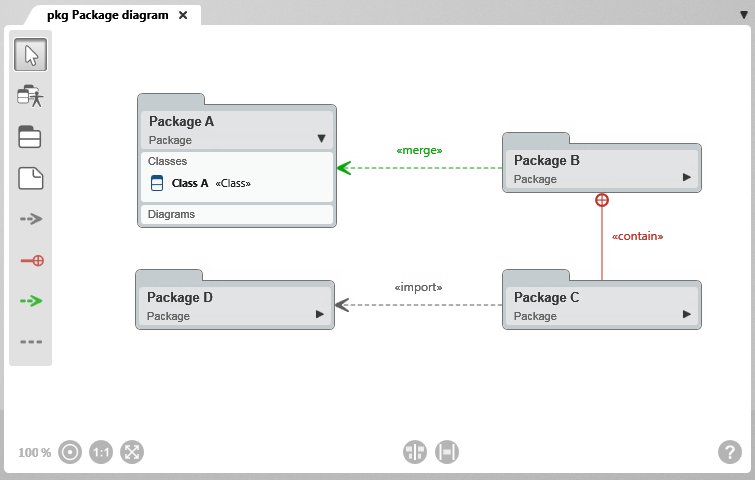
Toolbar
A toolbar is available on the left side of the diagram for working in the diagram. This toolbar is used to create elements and relationships and to add existing elements to the diagram. Which elements and relationships can be created with a button is shown in a tooltip when you move the mouse over a button.
Elements that are created in a diagram are created in the package in which the diagram is also located.
Alternatively, packages from the project can also be added to the diagram via drag & drop from a view or from the Explorer.
Permissible Diagram Elements
Not all element types can be used in this diagram type. The diagram elements that are permitted are determined by the UML modeling standards and the underlying modeling rules. Accordingly, the diagram type supports only the designated element types to enable consistent and traceable modeling.
New elements are always created according to the same principle: Click the button and then click in the diagram. A creation dialog opens, and as soon as the dialog is confirmed, the element is displayed in the diagram.

White arrow
With the selection tool (arrow), you can:
- Move the diagram background: Click the diagram background and drag it to another position while holding down the left mouse button.
- Edit diagram elements and relationships: Right-click a diagram element or relationship to open the context menu.
- Select diagram elements: Hold down the Shift key and use the left mouse button to draw a frame around the desired element nodes. Selected nodes are highlighted. Click the diagram background to clear the selection.

Add Existing Elements
Allows existing packages of the system to be added to the diagram.

Create package
Used to create a package.
Procedure for creating: Click the button and then click the diagram background.
Representation: Package node
Supported link: Package

Create Note
Used to create a note to provide additional information about the diagram or a diagram element.
Procedure for creating: Click the button and then click the diagram background.
Representation: Note node
Supported link: Possible with all permissible diagram elements

Create Import Relationship
Shows that all public types of one package are available in another package.
The default stereotype is «import» and is displayed on the relationship line. The name can be changed.
Procedure for creating: First click the package that is to import another package and then the package to be imported.
Representation: dashed gray line with an arrow
Arrow direction: The arrowhead points to the imported package

Create Containment Relationship
Shows the different hierarchy levels between packages.
The default stereotype is «contain» and is displayed on the relationship line.
Procedure for creating: First click the package that is to contain another package and then the contained package.
Representation: dashed red line with a crosshair
Arrow direction: The crosshair points to the target package

Create Merge Relationship
Shows that a package incorporates and extends the contents of another package.
The default stereotype is «merge» and is displayed on the relationship line. The name can be changed.
Procedure for creating: First click the target package (receives the content) and then the source package (provides the content).
Representation: dashed green line with an arrow
Arrow direction: The arrowhead points to the package whose content is incorporated

Create Note Relationship
Connects a note to another diagram element.
Procedure for creating: Click the note and then click the element node that is described in more detail by the note.
Representation: gray dashed line