
The Class Diagram
In the diagram, you can represent classes, requirements, and relationships – such as aggregations, associations, and generalizations. These show how the classes communicate with each other and how properties or behavior are inherited from one class to another.
The diagram
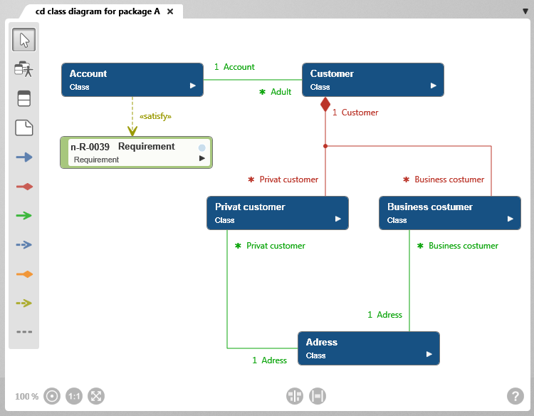
Toolbar
A toolbar is available on the left side of the diagram for working in the diagram. This toolbar is used to create elements and relationships and to add existing elements to the diagram. Which elements and relationships can be created with a button is shown in a tooltip when you move the mouse over a button.
Elements that are created in a diagram are created in the package in which the diagram is also located.
Alternatively, elements of the class diagram can also be added to the diagram via drag & drop from a view or any package.
Permissible Diagram Elements
Not all element types can be used in this diagram type. The diagram elements that are permitted are determined by the UML modeling standards and the underlying modeling rules. Accordingly, the diagram type supports only the designated element types to enable consistent and traceable modeling.
The toolbar differs between the Web Client and the Desktop Client.
In the Desktop Client, all buttons provided by the respective diagram type for creating elements and relationships are displayed.
In the Web Client, the toolbar has a more compact layout. Only some of the buttons are displayed directly. Additional element types and relationships are grouped and can be accessed via the context menu of a button. Buttons with additional options are indicated by a dot in the lower-right corner.
New elements are always created according to the same principle: Click the button and then click in the diagram. A creation dialog opens, and as soon as the dialog is confirmed, the element is displayed in the diagram.

White arrow
With the selection tool (arrow), you can:
- Move the diagram background: Click the diagram background and drag it to another position while holding down the left mouse button.
- Edit diagram elements and relationships: Right-click a diagram element or relationship to open the context menu.
- Select diagram elements: Hold down the Shift key and use the left mouse button to draw a frame around the desired element nodes. Selected nodes are highlighted. Click the diagram background to clear the selection.

Add Existing Elements

Create class
A class describes a set of objects that are characterized by common properties (attributes) and identical methods, have similar relationships to other objects, and fulfill a common semantic purpose.
When collapsed, a class displays its name and stereotype (Class); when expanded, it additionally displays the elements it contains.
Procedure for creating: Click the button and then click the diagram background.
Representation: Class node
Supported link: Class, requirement

Create Note
Used to create a note to provide additional information about the diagram or a diagram element.
Procedure for creating: Click the button and then click the diagram background.
Representation: Note node
Supported link: Possible with all permissible diagram elements

Create Generalization
Shows a relationship between a general and a specialized class. The specialized class inherits all properties and behavior of the general class and also has additional behavior and properties. If the superclass is an interface, the relationship line is displayed as a dashed line.
Procedure for creating: First click the general class and then the specialized class.
Representation: blue line with a closed arrowhead
Arrow direction: The arrowhead points to the general class

Create Aggregation
Defines a “consists-of” relationship between an aggregate class and its part classes.
Procedure for creating: First click the aggregate class and then the part class. Then open the relationship editing dialog and set the aggregation type to Aggregation. Here you can also specify roles and multiplicity.
Representation: red line with a diamond at the aggregate class
The multiplicity and role names are displayed on the relationship line.
Arrow direction: The diamond points to the aggregate class
Create Composition
A composition is a special form of aggregation in which the lifetime of the parts is tied to that of the whole. If the aggregate class is deleted, the part classes are also deleted.
Procedure for creating: First click the aggregate class and then the part class. Then open the relationship editing dialog and specify the roles and multiplicity.
Representation: red line with a filled diamond at the aggregate class
The multiplicity and role names are displayed on the relationship line.
Arrow direction: The diamond points to the aggregate class

Create Association
An association shows that the objects of one class are related to and communicate with the objects of another class.
Procedure for creating: First click one class and then the other class. Then open the relationship editing dialog and specify the roles and multiplicity.
Representation: green line
The multiplicity and role names are displayed on the relationship line.

Create Dependency
Shows that one class uses another class and therefore depends on it.
The default stereotype is «DependsRelationship» and is displayed on the relationship line. The name can be changed.
Procedure for creating: First click the class that uses another class and then the class on which it depends.
Representation: dashed blue line with an arrowhead
Arrow direction: The arrowhead points to the class on which it depends

Create Extend Relationship
Expresses that a class is functionally extended by allowing additional, optional elements to be assigned without changing the existing structure.
Procedure for creating: First click the extending class and then the class to be extended.
Representation: orange line with a diamond
Arrow direction: The diamond points to the extended class

Create Satisfy Relationship
Shows which requirement(s) the class satisfies.
The default stereotype of the relationship is «satisfy» and is displayed on the relationship line. The name can be changed.
Procedure for creating: Click a class and then a requirement.
Representation: olive-green dashed line with an arrow
Arrow direction: The arrowhead points to the requirement to be satisfied

Create Note Relationship
Connects a note to another diagram element.
Procedure for creating: Click the note and then click the element node that is described in more detail by the note.
Representation: gray dashed line