Working in diagrams
Diagrams can be opened with a double-click or via the context menu with Show.
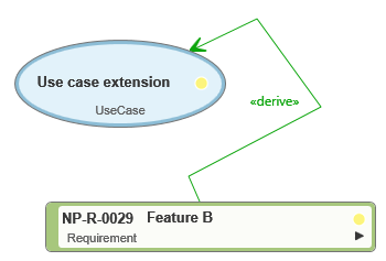
Create elements and relationships
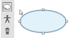
The modeling area has the same structure in all diagrams. On the left-hand side, there is a gray toolbar that you can use to create the diagram elements. When you move the mouse over the buttons, you’ll see what you can create with them. After the elements have been placed in the diagram, they can be linked to each other using corresponding relationships. A modeling wizard helps you choose the right relationships, as they cannot be created indiscriminately.
When you create relationships between elements, the tabs for each element fill automatically. If, for example, you remove a goal in the editing dialog of a requirement, this relationship also disappears from all diagrams in which it is represented. The same applies if you delete elements from the project.
Move diagram area
By pressing and holding the mouse button, the diagram can be moved freely in all directions.
Zoom diagram
Use the mouse scroll wheel to enlarge or reduce the diagram. You can also set the zoom factor by entering the percentage size at the bottom left of the diagram. A click on the button 1:1 restores the original size. The Fit Diagram to Screen button scales the diagram to the current window size.

Move elements
All diagram elements can be moved to the desired position with the mouse. To do this, the arrow button must be activated in the diagram toolbar.
All diagram elements can be moved to the desired position with the mouse. The arrow button must be activated in the toolbar of the active diagram window. As soon as you move over an element, the mouse pointer changes shape and becomes a quadruple arrow. Click on the desired element with the left mouse button and keep the button pressed. Release the mouse button when the desired position is reached. If you want to move several diagram elements, hold down the Shift key and select the desired area while holding down the left mouse button. Then click on an element within the selected range until the quad arrow appears and move the elements to the desired position.
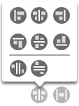
In the lower area you will find buttons that expand as you move the mouse over them. With these buttons you can distribute the diagram elements horizontally and vertically on the surface and align them with each other.
Add existing elements to a diagram
Elements from the tree can be dragged and dropped from a view directly into a diagram. For example, you can move a requirement to a requirement diagram or a goal to a goal diagram. In all diagrams, you can use the Add Existing Elements button to place multiple elements in the diagram simultaneously. To do this, first click on the button and then on a free space in the diagram.
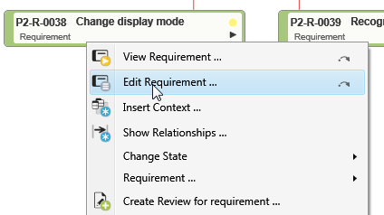
Edit diagram elements
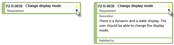
All diagram elements and their relationships have a context menu. To open it, right-click an element or relationship line. To edit an element or relationship in the chart, choose Edit from the shortcut menu.
All diagram elements and their relationships have a context menu. To open it, right-click an element or relationship line. To open the properties dialog of an element, choose Edit from the context menu. You can use the small triangle in the header of diagram symbols to open and close it.
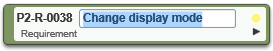
Most diagrams can be opened or closed. To do this, click on the small triangle at the top of the diagrams.
If you want to rename an element, double-click the name to activate the edit mode.
In use case diagrams, click on a symbol with the mouse and move the mouse to its edge. You can change the size of the symbol by using the handles displayed.
Print diagram or copy as image
A right-click on the background of a diagram opens a menu with commands for printing or copying the diagram to the clipboard.
Hide or delete elements
You can delete the item and irrevocably remove it from the project. Use the context menu command Delete to do this. Or use the Remove from Diagram command. This deletes the element from the diagram, but not from the project. The relationships you have created with other elements are also preserved. Elements hidden from a diagram can be placed back in the diagram using drag & drop from the Products window, the Add Existing Elements button, or the Insert Context command.
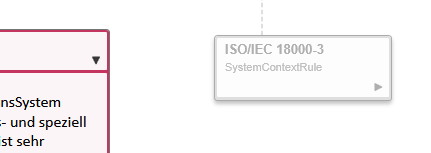
Insert Context
Elements in a diagram can have relationships to elements that were not previously included in the diagram. To find out what these are, execute the Insert Context command in the context menu of an element. In the subsequent dialog box, you can transfer all elements that have not yet been displayed in the diagram, including their relationships to the source element, directly to the diagram.
Straighten relationships
Relationships, e.g. in use case diagrams, can be straightened with a simple mouse click. Wherever a relationship line makes a “bend”, you can remove it by double-clicking on the corresponding position in the relationship line. Alternatively, execute the command Rearrange in the context menu of the relationship line.