
The Requirements Diagram
A requirement diagram is used to visualize requirements for a system. It shows how requirements are linked to one another and how they relate to test cases, stakeholders, or system components.
The diagram is primarily used to present requirements clearly and structure them in a traceable manner. This makes it possible to identify dependencies, uncover gaps or contradictions, and ensure the traceability of requirements. In this way, the requirement diagram supports the analysis, validation, and communication of requirements throughout the development process.
In the diagram, you can display and create requirements, test cases, stakeholders, and personas.
The diagram
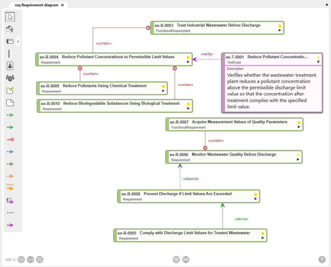
Toolbar
A toolbar is available on the left side of the diagram for working in the diagram. This toolbar is used to create elements and relationships and to add existing elements to the diagram. Which elements and relationships can be created with a button is shown in a tooltip when you move the mouse over a button.
Elements that are created in a diagram are created in the package in which the diagram is also located.
Alternatively, elements of the requirements diagram can also be added to the diagram via drag & drop from a view or any package.
Permissible Diagram Elements
Not all element types can be used in this diagram type. The diagram elements that are permitted are determined by the SysML modeling standards and the underlying modeling rules. Accordingly, the diagram type supports only the designated element types to enable consistent and traceable modeling.
The toolbar differs between the Web Client and the Desktop Client.
In the Desktop Client, all buttons provided by the respective diagram type for creating elements and relationships are displayed.
In the Web Client, the toolbar has a more compact layout. Only some of the buttons are displayed directly. Additional element types and relationships are grouped and can be accessed via the context menu of a button. Buttons with additional options are indicated by a dot in the lower-right corner.
New elements are always created according to the same principle: Click the button and then click in the diagram. A creation dialog opens, and as soon as the dialog is confirmed, the element is displayed in the diagram.

White arrow
With the selection tool (arrow), you can:
- Move the diagram background: Click the diagram background and drag it to another position while holding down the left mouse button.
- Edit diagram elements and relationships: Right-click a diagram element or relationship to open the context menu.
- Select diagram elements: Hold down the Shift key and use the left mouse button to draw a frame around the

Add Existing Elements
Opens a selection dialog to add existing system context diagram elements to the diagram.

Create Requirement
A requirement is a property or condition that a system or system component must fulfill.
Procedure for creating: Click the button and then click the diagram background.
Representation: Requirement node
Supported link: Test case, stakeholder

Create Region
Divides the diagram into areas and groups requirements.
Elements located within a region are contained in a package, if one is defined. If no package is assigned to the region, elements from different packages can be dragged into a region. Regions cannot be nested.
Procedure for creating: Click the button and drag to draw a frame while holding down the mouse button.

Create Persona
A persona is a fictional person with specific characteristics and behavior patterns who represents a prototype for a group of real users.
Procedure for creating: Click the button and then click the diagram background.
Representation: Persona node
Supported link: Requirements, stakeholder

Create Stakeholder
Stakeholders are individuals or organizations that have a specific interest in the system to be created and therefore in the fulfillment of specific requirements.
Procedure for creating: Click the button and then click the diagram background.
Representation: Stakeholder node
Supported link: Requirement, stakeholder

Create Test Case
A test case is required to verify requirements with regard to their specification.
Procedure for creating: Click the button and then click the diagram background.
Representation: Test case node
Supported link: Requirement, test case

Create Note
Used to create a note to provide additional information about the diagram or a diagram element.
Procedure for creating: Click the button and then click the diagram background.
Representation: Note node
Supported link: Possible with all permissible diagram elements

Create Refine Relationship
Shows that a requirement is described in greater detail by a use case diagram.
The default stereotype of this relationship type is «refine» and is displayed on the relationship line. The name can be changed.
Procedure for creating: Click first on the use case diagram and then on the requirement.
Representation: Dashed green line with arrow
Arrow direction: Arrowhead points to the requirement

Create Derive Relationship
Shows that a requirement is derived from one or more other requirements.
The default stereotype of the relationship is «derive» and is displayed on the relationship line. The name can be changed.
Procedure for creating: Click first on the derived requirement and then on the requirement from which it is derived.
Representation: Green line with arrow
Arrow direction: Arrowhead points to the requirement from which a requirement was derived

Create Containment Relationship
Shows that a requirement is refined by other requirements. The relationship also expresses that a higher-level requirement is fulfilled only when all of its subordinate requirements are fulfilled.
The default stereotype of this relationship type is «contain» and is displayed on the relationship line. The name can be changed.
Procedure for creating: Click first on the higher-level requirement and then on the refined requirement.
Representation: Red line with crosshair
Crosshair: Crosshair is located at the higher-level requirement

Create Dependency Relationship
Expresses that a requirement depends on another requirement.
The default stereotype of this relationship type is «depend» and is displayed on the relationship line. The name can be changed.
Procedure for creating: Click first on the dependent requirement and then on the requirement on which it depends.
Representation: Dashed blue line with arrow
Arrow direction: Arrowhead points to the requirement on which other requirements depend

Create Interest Relationship
Illustrates a stakeholder’s interest in the implementation of a requirement. A stakeholder’s interest in a requirement is weighted and indicated as Weight on the relationship line.
The default stereotype of this relationship type is «interested» and is displayed on the relationship line. The name can be changed.
Procedure for creating: Click first on the stakeholder and then on the requirement.
Representation: Dashed gray line with arrow
Arrow direction: Arrowhead points to the requirement

Create Needs Relationship
Illustrates that a persona needs the implementation of a requirement to fulfill their specific needs.
The default stereotype of this relationship type is «need» and is displayed on the relationship line. The name can be changed.
Procedure for creating: Click first on the persona and then on the requirement.
Representation: Dashed orange line with arrow
Arrow direction: Arrowhead points to the requirement

Create Knows Relationship
This relationship is created between stakeholders to illustrate that stakeholders know each other. The relationship can be specified in both directions. The “relationship” that one stakeholder has with the other stakeholder can optionally be specified and is indicated as Role on the relationship line.
The default stereotype of this relationship type is «knows» and is displayed on the relationship line. The name can be changed.
Procedure for creating: Click first on the stakeholder who knows the other stakeholder and then on the stakeholder with whom the relationship exists.
Representation: Orange line with arrow
Arrow direction: Arrowhead points to the stakeholder whom the stakeholder knows

Create Requirement Verify Relationship
Connects a requirement to a test case and shows that the requirement is verified by the test case.
The default stereotype of this relationship type is «verify» and is displayed on the relationship line. The name can be changed.
Procedure for creating: Click first on the test case and then on the requirement.
Representation: Dashed purple line with arrow
Arrow direction: Arrowhead points to the requirement to be verified

Create Note Relationship
Connects a note to another diagram element.
Procedure for creating: Click the note and then click the element node that is described in more detail by the note.
Representation: gray dashed line

Create Test Case Control Flow
Connects one test case to another test case and shows the order in which test cases are to be executed.
The default stereotype of this relationship type is «control flow» and is displayed on the relationship line. The name can be changed.
Procedure for creating: Click a test case and then click the test case that is to be tested next.
Representation: Purple line with arrow
Arrow direction: Arrowhead points to the subsequent test case