
The Use Case Diagram
The diagram is primarily used to describe the functions and usage scenarios of a system from the users’ perspective. It shows what the system does and the context in which these interactions take place.
In addition, the use case diagram helps to identify, understand, and structure requirements before the actual system architecture is modeled. It also serves as a central basis for communication between specialist departments, users, and developers.
In the diagram, you can represent and create actors, use cases, system boundaries, relationships between use cases (e.g., include or extend), as well as requirements.
The diagram
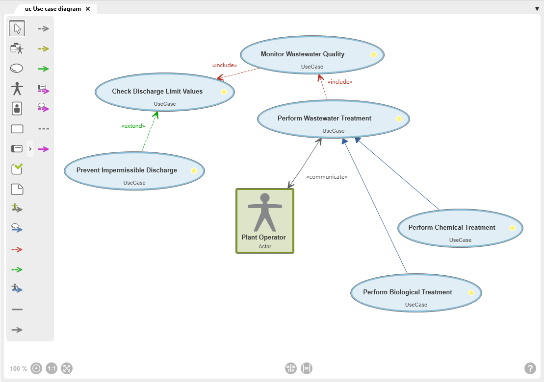
Toolbar
A toolbar is available on the left side of the diagram for working in the diagram. This toolbar is used to create elements and relationships and to add existing elements to the diagram. Which elements and relationships can be created with a button is shown in a tooltip when you move the mouse over a button.
Elements that are created in a diagram are created in the package in which the diagram is also located.
Alternatively, elements of the use case diagram can also be added to the diagram via drag & drop from a view or any package.
Permissible Diagram Elements
Not all element types can be used in this diagram type. The diagram elements that are permitted are determined by the UML modeling standards and the underlying modeling rules. Accordingly, the diagram type supports only the designated element types to enable consistent and traceable modeling.
The toolbar differs between the Web Client and the Desktop Client.
In the Desktop Client, all buttons provided by the respective diagram type for creating elements and relationships are displayed.
In the Web Client, the toolbar has a more compact layout. Only some of the buttons are displayed directly. Additional element types and relationships are grouped and can be accessed via the context menu of a button. Buttons with additional options are indicated by a dot in the lower-right corner.
New elements are always created according to the same principle: Click the button and then click in the diagram. A creation dialog opens, and as soon as the dialog is confirmed, the element is displayed in the diagram.

White arrow
With the selection tool (arrow), you can:
- Move the diagram background: Click the diagram background and drag it to another position while holding down the left mouse button.
- Edit diagram elements and relationships: Right-click a diagram element or relationship to open the context menu.
- Select diagram elements: Hold down the Shift key and use the left mouse button to draw a frame around the

Add Existing Elements
Opens a selection dialog to add existing system context diagram elements to the diagram.

Create Use Case
A use case shows the functionality or a specific behavior of a system – in interaction with an actor.
Procedure for creating: Click the button and then click the diagram background.
Representation: Use case node
Supported link: Use case, actor, requirement, test case, persona scenario

Create Actor
An actor represents a person or an external system that interacts with a system.
Procedure for creating: Click the button and then click the diagram background.
Representation: Actor node
Supported link: Actor, use case, persona

Create Persona
A persona represents a real user group with the same goals, interests, or wishes. Personas are based on the behavioral patterns of real people and can be described in great detail through specific character traits, personal values, and goals.
Procedure for creating: Click the button and then click the diagram background.
Representation: Persona node
Supported link: Persona scenarios, actor

Create Persona Scenario
A scenario describes, by way of example, how a persona “experiences” a specific use case.
Procedure for creating: Click the button and then click the diagram background.
Representation: Scenario node
Supported link: Persona, use case

Create Requirement
A requirement shows the use case by which it is implemented. A use case can cover multiple requirements.
Procedure for creating: Click the button and then click the diagram background.
Representation: Requirement node
Supported link: Test case, use case

Create Test Case
A test case is required to verify use cases with regard to their specification.
Procedure for creating: Click the button and then click the diagram background.
Representation: Test case node
Supported link: Requirement, use case, test case

Create Note
Used to create a note to provide additional information about the diagram or a diagram element.
Procedure for creating: Click the button and then click the diagram background.
Representation: Note node
Supported link: Possible with all permissible diagram elements

Create Communication Relationship
Shows which actor performs a use case.
The default stereotype of the relationship is «communicate» and is displayed on the relationship line. The name can be changed. The multiplicity is specified in the relationship editing dialog.
Procedure for creating: Click an actor and then click a use case.
Representation: gray line with an arrow on each end
Arrow direction: The arrowheads point to the use case and the actor
The multiplicity is displayed on the relationship line for both elements.

Create Generalization (Use Case)
Connects two use cases and represents the relationship between a general and a specialized use case.
Specialized use cases inherit all properties of the general use case.
Procedure for creating: First click the general use case and then the specialized use case.
Representation: blue line with a closed arrowhead
Arrow direction: The arrowhead points to the general use case

Create Include Relationship
Connects two use cases, where one use case includes another in order to separate out a common use case that is an integral part of the parent use case.
The default stereotype is «include» and is displayed on the relationship line. The name can be changed.
Procedure for creating: First click the general use case and then the use case that is to be executed as part of it.
Representation: red dashed line with an arrow
Arrow direction: Points to the use case that is executed as part of it

Create Extend Relationship
Connects two use cases, where one use case is extended by another use case.
The default stereotype is «extend» and is displayed on the relationship line. The name can be changed.
Procedure for creating: First click the extending use case and then the use case that is extended.
Representation: dashed green line with an arrow
Arrow direction: The arrowhead points to the use case that is extended

Create Actor Generalization
Connects two actors through a generalization and visualizes a relationship between a general and a specialized actor. Specialized actors inherit all properties of the general actor.
Procedure for creating: First click the general actor and then a specialized actor.
Representation: blue line with an arrow
Arrow direction: The arrowhead points to the general actor

Create Persona-Actor Relationship
Shows which persona assumes the role of the actor when performing a use case.
The default stereotype is «represent» and is displayed on the relationship line. The name can be changed.
Procedure for creating: First click the persona and then the actor.
Representation: gray line

Create Persona-Scenario Relationship
Connects a persona to a persona scenario. It shows which possible scenarios a persona experiences during a use case.
The default stereotype is «scenario» and is displayed on the relationship line. The name can be changed.
Procedure for creating: First click the persona and then the persona scenario.
Representation: gray line with an arrow
Arrow direction: The arrowhead points to the persona scenario

Create Specialization Relationship
Shows which use case is “experienced” in the persona scenario.
The default stereotype is «spezialize» and is displayed on the relationship line. The name can be changed.
Procedure for creating: First click the persona scenario and then the use case.
Representation: gray dashed line with an arrow
Arrow direction: The arrowhead points to the use case

Create Satisfy Relationship
Connects a requirement to the use case and shows which use case satisfies a requirement.
The default stereotype is «satisfy» and is displayed on the relationship line. The name can be changed.
Procedure for creating: First click the use case and then the requirement.
Representation: olive-green dashed line with an arrow
Arrow direction: The arrowhead points to the requirement

Create Derive Relationship
Shows that a requirement is derived from one or more use cases.
The default stereotype of this relationship type is «derive» and is displayed on the relationship line. The name can be changed.
Procedure for creating: First click the requirement and then the use case.
Representation: solid green line with an arrow
Arrow direction: The arrowhead points to the use case

Create Requirement Verify Relationship
Connects a requirement to a test case and shows that the requirement is verified by the test case.
The default stereotype of this relationship type is «verify» and is displayed on the relationship line. The name can be changed.
Procedure for creating: Click first on the test case and then on the requirement.
Representation: Dashed purple line with arrow
Arrow direction: Arrowhead points to the requirement to be verified

Create Use Case Verify Relationship
Connects a use case to a test case. A verification relationship shows that a use case is verified by a test case.
The default stereotype of this relationship type is «verify» and is displayed on the relationship line. The name can be changed.
Procedure for creating: First click the test case and then the use case.
Representation: dashed purple line with an arrow
Arrow direction: The arrowhead points to the use case to be verified.

Create Test Case Control Flow
Connects one test case to another test case and shows the order in which test cases are to be executed.
The default stereotype of this relationship type is «control flow» and is displayed on the relationship line. The name can be changed.
Procedure for creating: Click a test case and then click the test case that is to be tested next.
Representation: Purple line with arrow
Arrow direction: Arrowhead points to the subsequent test case

Create Note Relationship
Connects a note to another diagram element.
Procedure for creating: Click the note and then click the element node that is described in more detail by the note.
Representation: gray dashed line