The System Context Diagram
In the system context diagram, the boundaries of the system are defined and its context and interaction partners are displayed. What belongs to the system and what lies outside the system boundary is clarified, and which aspects the planned system should cover and which it should not.
System context diagrams are particularly suitable for communication with stakeholders and specialist departments in the initial phase of a project, when the system and its context are to be delimited, due to their clear presentation.
This diagram type also shows which information flows between the system and its context elements and which framework conditions, standards and rules must be taken into account in system development.
The diagram can be opened:
- in the context menu of a package with the command Create diagram/ System context diagram
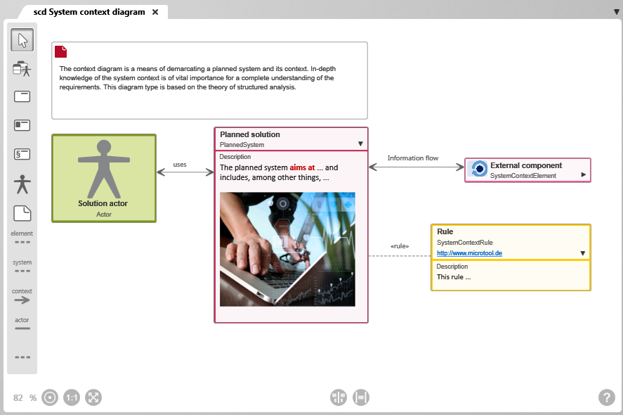
The diagram
The most important editing functions
| Add Existing Elements Makes it possible to integrate existing system contexts, system context elements, actors or system context rules in the diagram. | |
| Create System Context Element Creates a new system context element and adds it directly to the diagram. A system context element represents a part of the system that is either inside or outside the system context. System context elements that lie within the system context have the same color as the system context. Elements that lie outside the system context are displayed in gray. The symbol of a system context shows its name and stereotype when collapsed. Its default stereotype is «SystemContextElement». When expanded, its description is also displayed. You can use the small triangle to expand and collapse the symbol. |
|
| Create System Context Creates a new system context and adds it directly to the diagram. The system context module is the “center” of a system context diagram. It represents the system to be developed and describes the scope as well as the tasks and functions of the system. The symbol of a system context shows its name and stereotype in the collapsed state. Its standard stereotype is «PlannedSystem». When expanded, its description is also displayed. You can use the small triangle to expand and collapse the symbol. |
|
| Create Element-Rule Relationship Connects a rule with a system context element. In many areas, systems must comply with legal regulations or standards. You can model the framework conditions and rules to be observed in the system context diagram and link them to the system context or system context elements. The name and stereotype of a rule are displayed when it is collapsed. Its default stereotype is «SystemContextRule». When expanded, a rule also displays its description. You can use the small triangle to expand and collapse the symbol. |
|
| Create Actor Creates a new actor and adds it directly to the diagram. | |
| Create Note Used to create a note. | |
| Create Element-Rule Relationship Connects a rule with a system context element. The relation line is a grey dashed line labeled Rule. | |
| Create System-Rule Relationship Creates a relationship between a rule and the system context. | |
| Create Information Flow Creates a relationship between the system context and a system context element. This type of relationship shows a flow of information between the system and its context elements. The relationship line of an information flow is a gray solid line. The standard description of the relationship is Information flow. |
|
| Create Interact Relationship Connects the system context and an actor by an interact relationship. The relationship arrow can be labeled to indicate, for example, the type of interaction. | |
| Create Note relationship Connects the note and an element from the diagram. |
Other commands
When you call the context menu in the diagram, additional commands are offered:
You can use Edit to edit the description, stereotypes, and user-defined properties of the diagram.
In particular, if you reference elements using the editing dialog and decide at a later point in time to represent this relationship in a diagram, you can do this using the Show Relationships command.
Drag and drop the elements into the diagram and call the command from the context menu. All relationships between the displayed elements are displayed.
If you call the command for a specific element, the dialog Transfer Relationships opens, where you can select the corresponding relationship from the list of all existing relationships.
With Rearrange Relationships, all relationships drawn in the diagram are arranged in such a way that they can be seen optimally.
You can use Share to send the diagram to other people. You can create a link or hyperlink, or an e-mail that contains a link.
With Print you open the printer settings and can then print the diagram from a printer of your choice.
Copy as image copies the image to the clipboard. You can then paste it into a PowerPoint slide or a Word document, for example.
Using Revisions you can create a revision for the diagram, call up the history or overwrite the current state with the revision created last.
The Go To command opens the Products view and highlights the selected item.